rudolf mittelmann
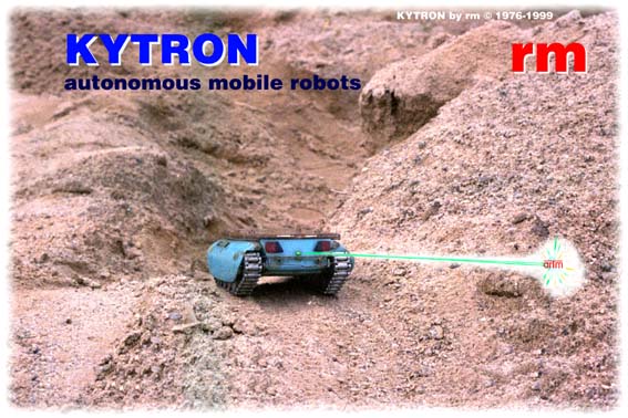
KYTRON
Content of this page:
What a KYTRON is...
What a KYTRON does...
The design of a KYTRON
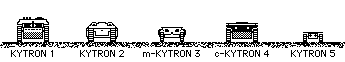
KYTRON 1
: The Big
KYTRON 2
: The Intelligent
m-KYTRON 3
: The Solar-Powered
c-KYTRON 4
: The SW-Controlled
KYTRON 5
: The Microbot
Pictures of KYTRONs
Circuits of KYTRONs and the K4 software
Simulation of KYTRONs
Hints for creating your own robots
Attention:
An
autonomous mobile robot
page just for fun.